pvOSPRay Basic Walk-Through
This demo provides a basic walk-through of how to enable and use pvOSPRay within ParaView. If you do not yet have a version of pvOSPRay installed on your system, you can follow these instructions for getting pvOSPRay.
In this demo, you will:
- Create a wavelet object drawn using the default ParaView rasterizer (jump to this step)
- Load the pvOSPRay plugin (jump to this step)
- Render the wavelet object using OSPRay (jump to this step)
- Change OSPRay settings to affect quality and performance (jump to this step)
Each demo image below is linked to a larger version for your reference. Just click the image to open the larger version.
Creating a Rasterized Object
The first task in this demo is to create a simple yet interesting object to render. The ParaView wavelet source is well-suited to this task, as it has more varied features than a simple geometric shape like a cone or sphere. However, the wavelet source creates a volume by default, so we will extract several isosurfaces from the volume to create our object.
| First, open ParaView. The images used in this demo are taken from a MacOSX build, but Linux and Windows builds are similar. You should see the ParaView workspace, similar to the image to the right. |
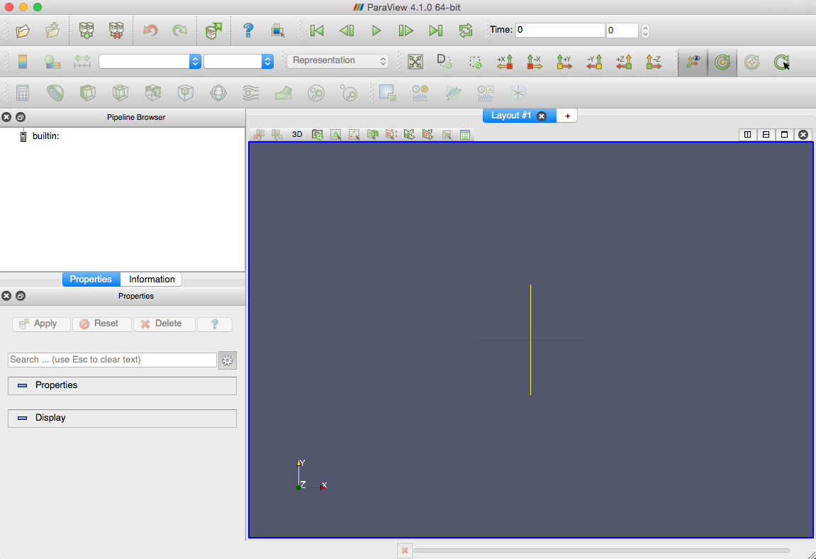
|
| Next, select the "Sources" menu from the ParaView menu bar (at the top of the application window in Linux and Windows, at the top of the desktop in MacOSX). In the Sources menu, select "Wavelet". |
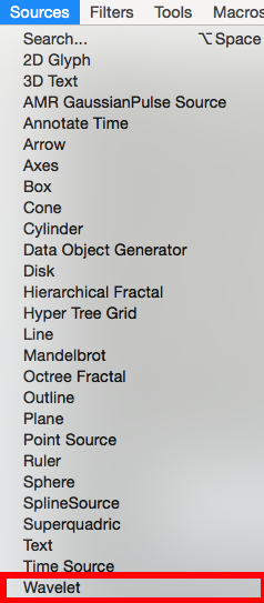
|
| This will create a Wavelet source in the ParaView Pipeline Browser and a wireframe of the wavelet volume in the Layout #1 render window. |
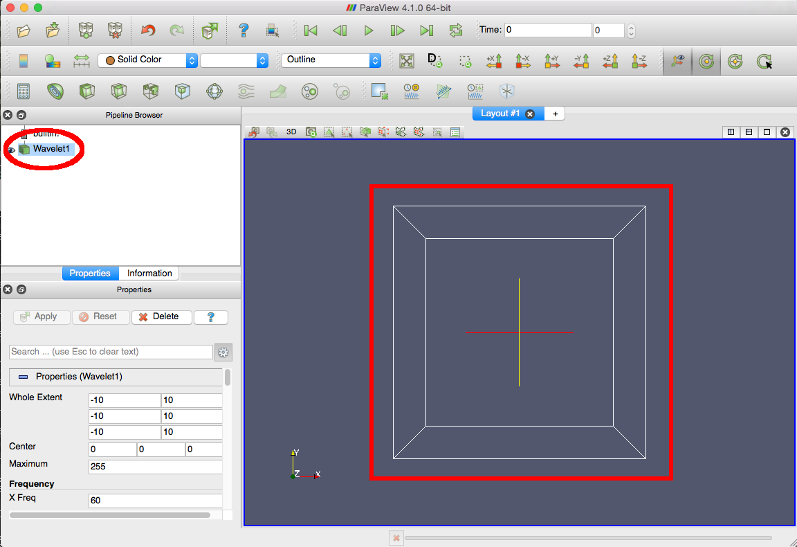
|
| Next, we will create a set of isosurfaces (also called "contours") in the wavelet data, which will provide visible surfaces to render. Click the "Contour" button in the ParaView toolbar (the concentric half-spheres icon to the right of the calculator icon). |
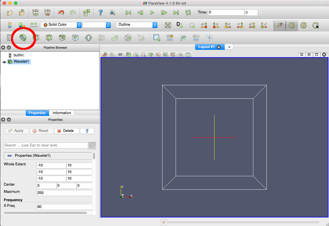
|
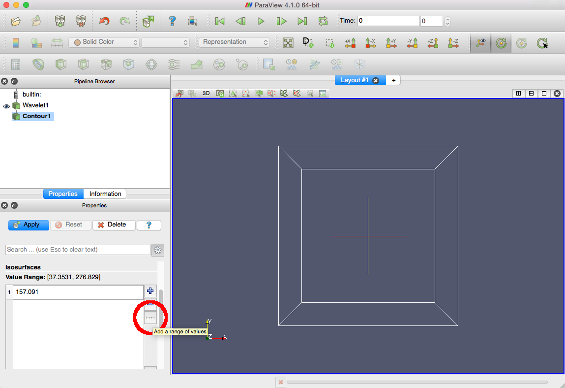
| We have now added a contour filter, which by default creates a single isosurface at the midpoint value of the dataset. However, we would like to generate several surfaces to better show the shading capabilities of OSPRay. Click the 'Add a range of values' button to the right of the Isosurfaces box in the Properties display. |
|
|
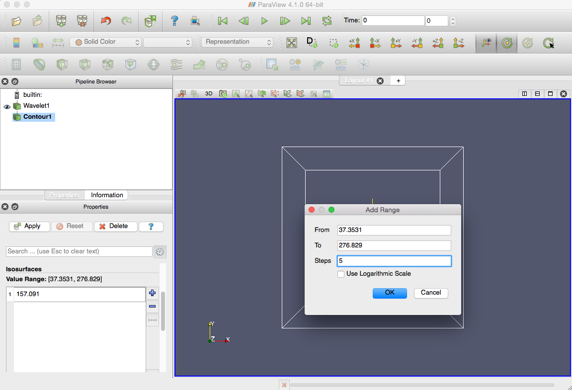
This opens the "Add Range" dialog. For this demo, we will change the number of steps to 5, rather than use the default of 10. (We encourage you to experiment both with the step value and the range endpoints to create different surfaces.) When you have adjusted the values to your liking, click the "OK" button.
|
|
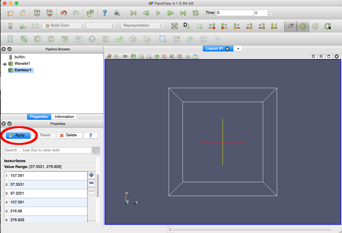
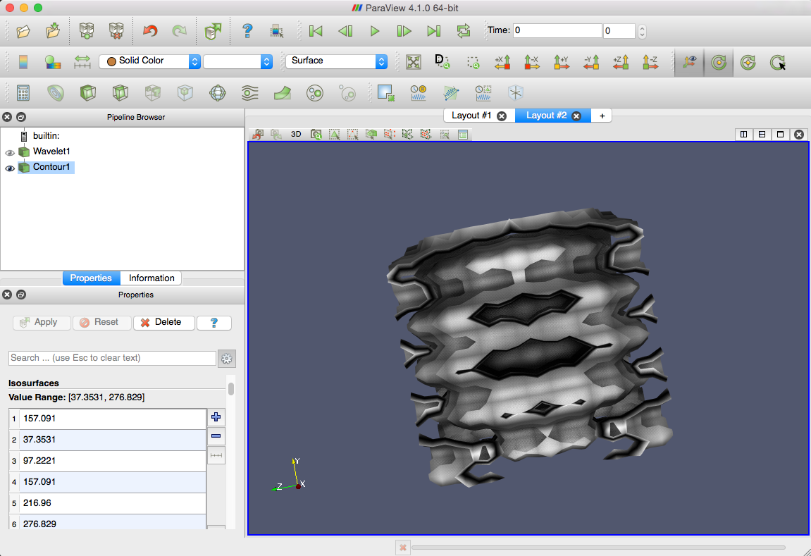
| The Isosurfaces box in the Properties display now contains five isovalues. Click the "Apply" button at the top of the Properties display to create the isosurfaces. |
|
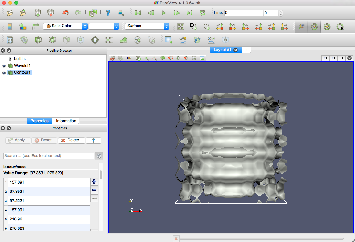
| The wavelet isosurfaces should now be rendered in the Layout #1 display window, similar to the image to the right. |
|
Loading the pvOSPRay plugin
The next task in this demo will load the pvOSPRay plugin so that you can render images using OSPRay. The plugin is not loaded by default, so we will use ParaView's dynamic plugin mechanism to load pvOSPRay.
|
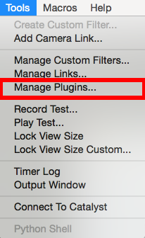
First, open the ParaView Plugin Manager dialog. Select the "Tools" menu from the ParaView menu bar (at the top of the application window in Linux and Windows, at the top of the desktop in MacOSX). In the Tools menu, select "Manage Plugins...". |
|
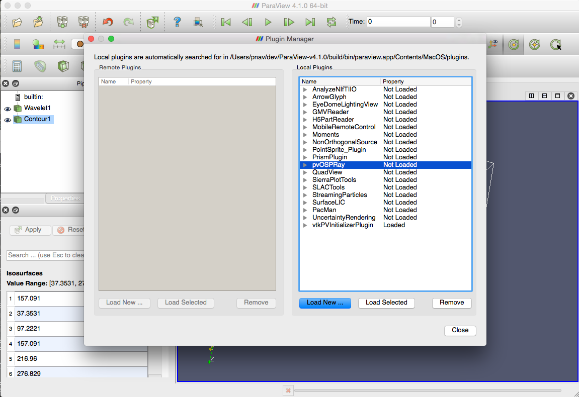
| This will open the ParaView Plugin Manager dialog. Find the pvOSPRay plugin in the Local Plugins list on the right. Select pvOSPRay by clicking on it. |
|
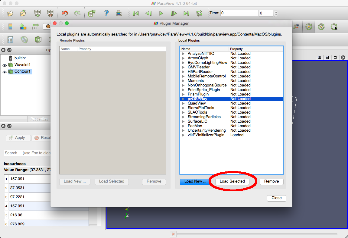
| After selecting pvOSPRay from the list, click the "Load Selected" button. |
|
|
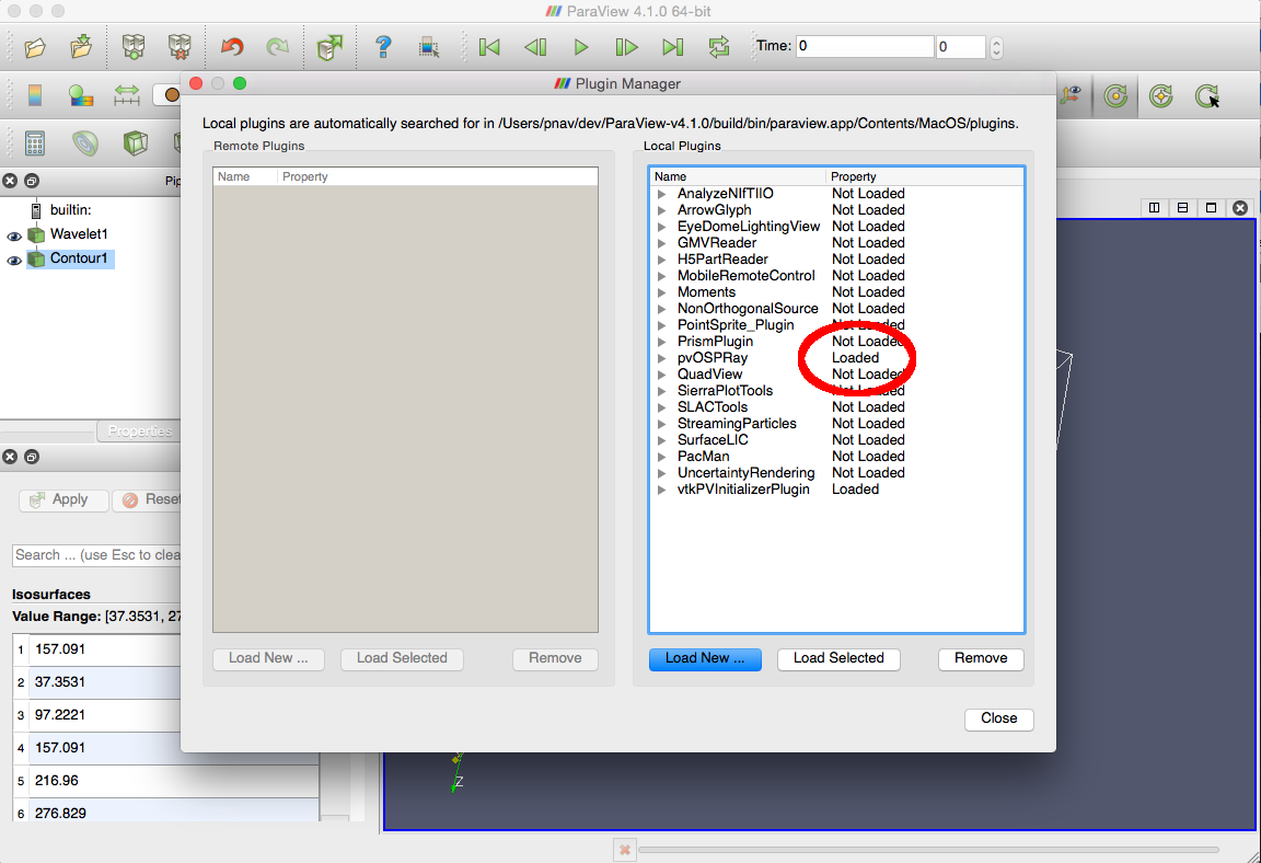
The Property value next to pvOSPRay should now show "Loaded", indicating that the plugin has successfully been connected to ParaView. Close the Plugin Manager dialog. OSPRay is now ready for use! |
|
Rendering using OSPRay
Loading the pvOSPRay plugin makes OSPRay rendering available, but you must explicitly open an OSPRay display to use it. This demo task will open an OSPRay display and render the wavelet object using the OSPRay ray tracer.
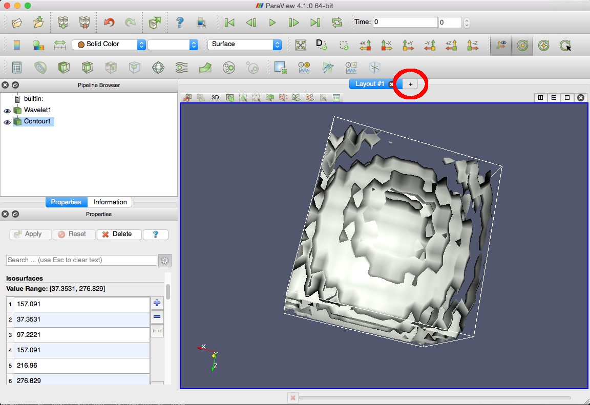
| First, create a new display layout. Select the "+" icon next to "Layout #1" above the display window to add a new display layout. |
|
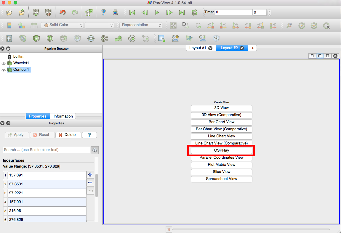
| This opens a blank display with various view options. Select "OSPRay" from the Create View list. |
|
|
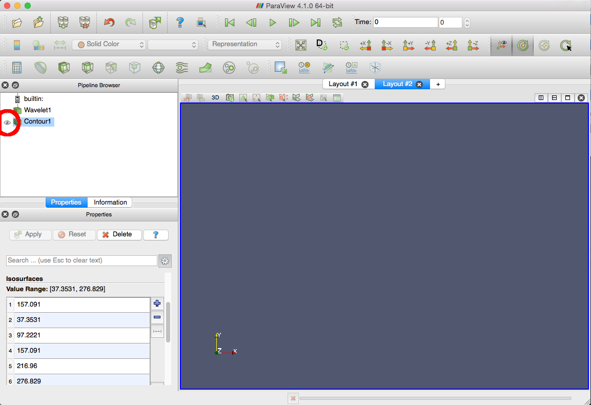
The OSPRay display is now open, but nothing is rendered yet, since all the pipeline objects in the new display are hidden by default. Show the wavelet isosurfaces by clicking on the eye icon next to the Contour in the Pipeline Browser. |
|
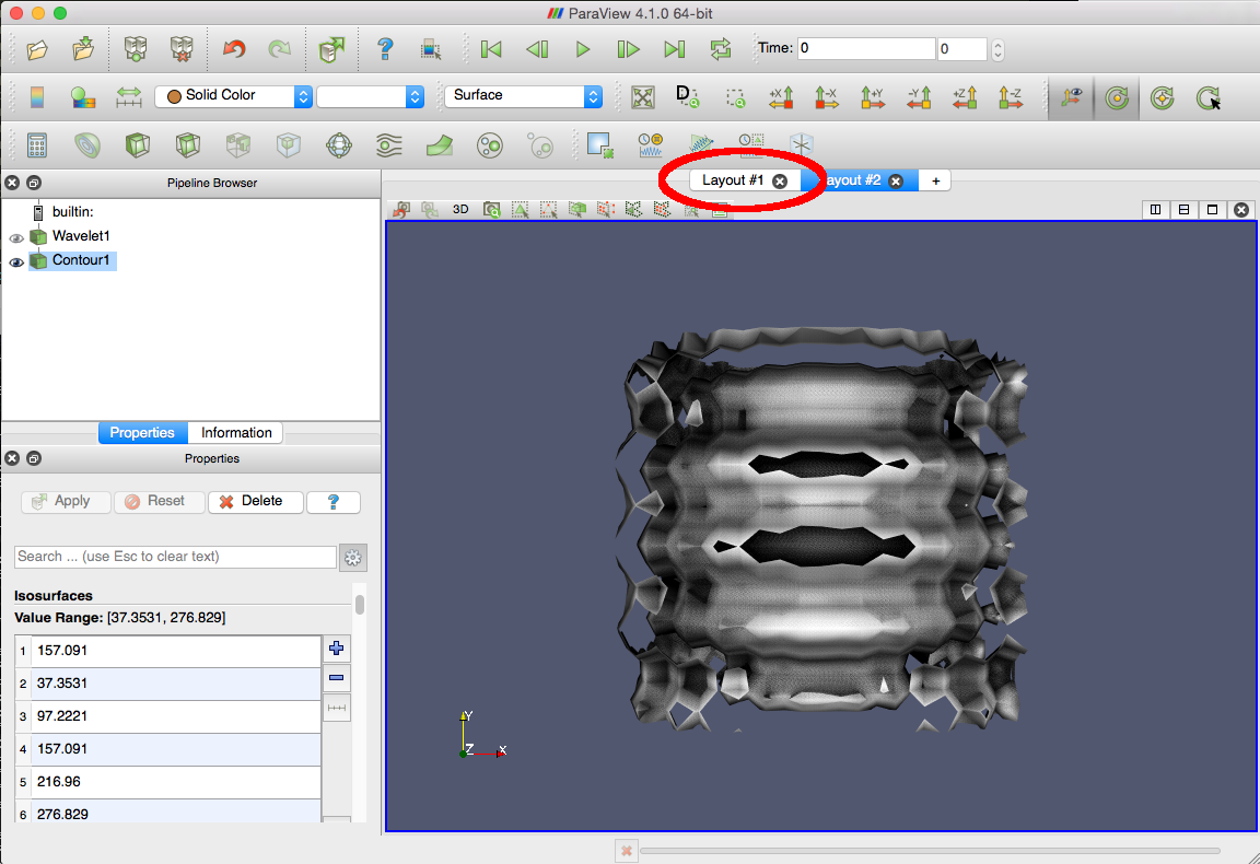
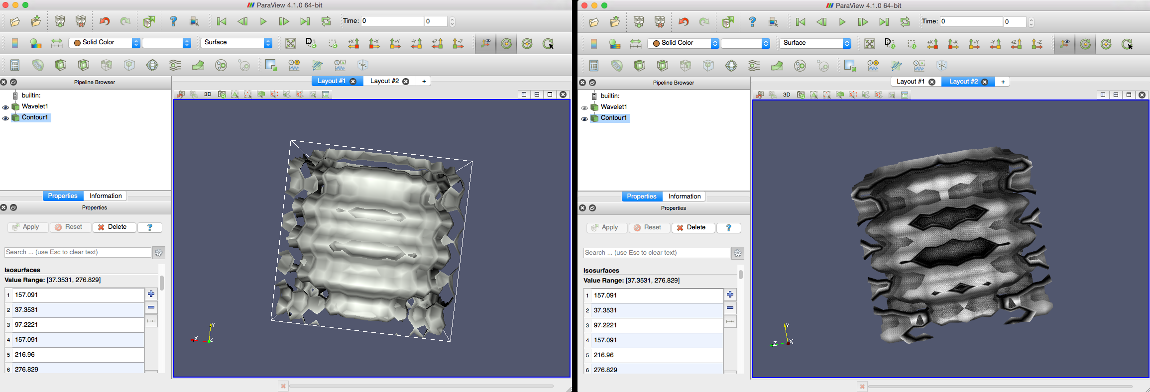
| The OSPRay-rendered wavelet surfaces are now displayed in Layout #2. You can swap between the raster version in Layout #1 and the ray-traced version in Layout #2 by clicking on the respective layout tabs. The active tab is highlighted (here, in blue). |
|
| The OSPRay renderer has Ambient Occlusion (AO) enabled by default. This shading technique creates realistic shadowing effects more efficiently than a full global illumination approximation. Notice that the surface texture and interior regions are much more apparent in the OSPRay ray traced images (right) than in the rasterized images (left). |
|
Changing OSPRay Settings
OSPRay has a number of settings that affect the speed and quality of the rendering. In general, higher-quality images take longer to produce. We recommend using efficient settings during data exploration, then increasing the quality settings for particular views of interest.
Most of OSPRay's settings are accessible through ParaView's toolbars and Properties display. However, a few are accessible only through the ParaView Application Preferences dialog. This final demo task will show you how to set these and their effects on the rendered image.
|
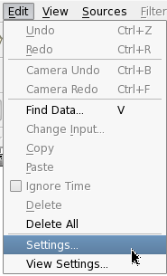
First, open the ParaView Settings dialog. In MacOSX, open the "ParaView" menu and select "Preferences..." (shown, left). In Linux, open the "Edit" menu and select "Settings..." (shown, right). |

|
|
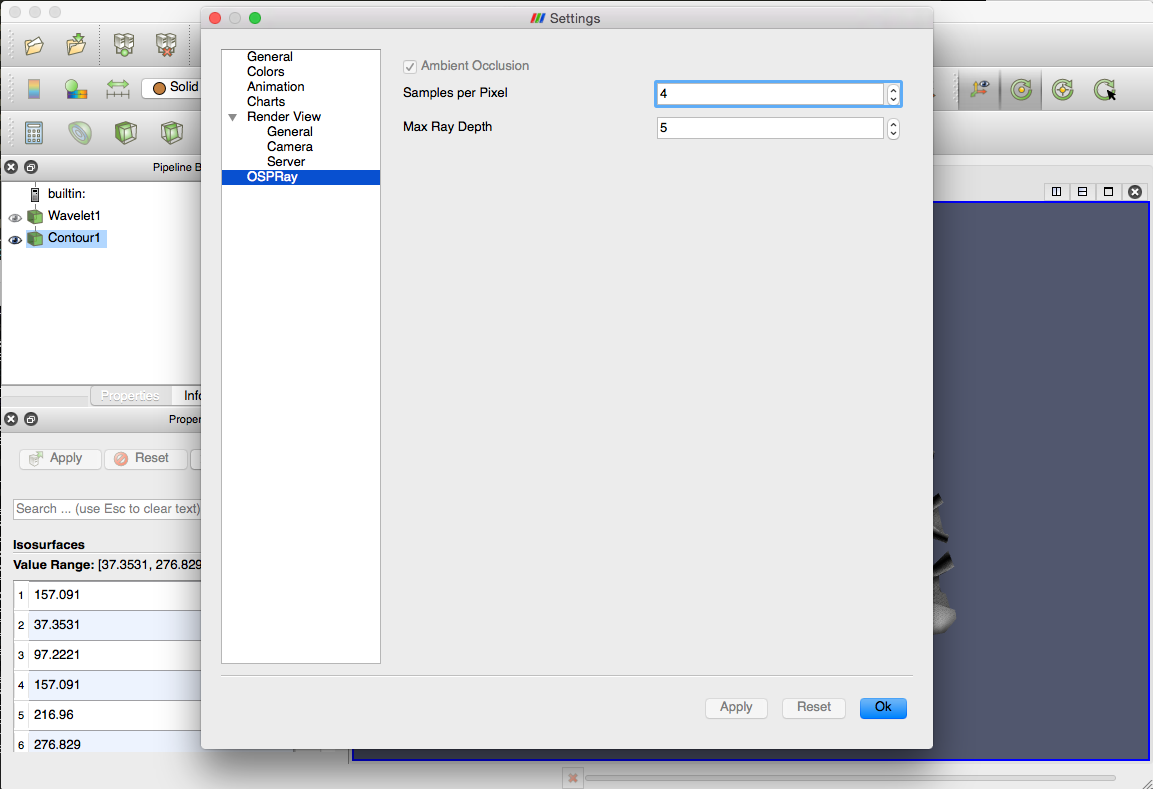
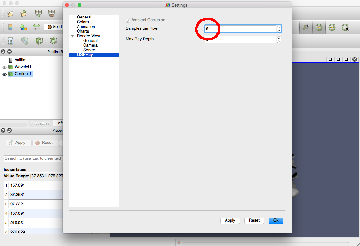
This opens the Settings dialog. Highlight "OSPRay" in the left-side menu to see the OSPRay-specific settings.
"Sampes per Pixel" sets the number of rays traced for each pixel in the displayed image.
"Max Ray Depth" sets the number of bounces the tracer allows before terminating a ray path. This setting applies to
special material properties that require additional sampling, such as reflective materials; or special lighting properties,
such as global illumination approximations. |
|
|
The OSPRay images to this point have used four (4) samples per pixel. Set the value to 64 to see the difference in image quality and frame rate. Click "OK" to close the dialog and to have the new settings take effect. |
|
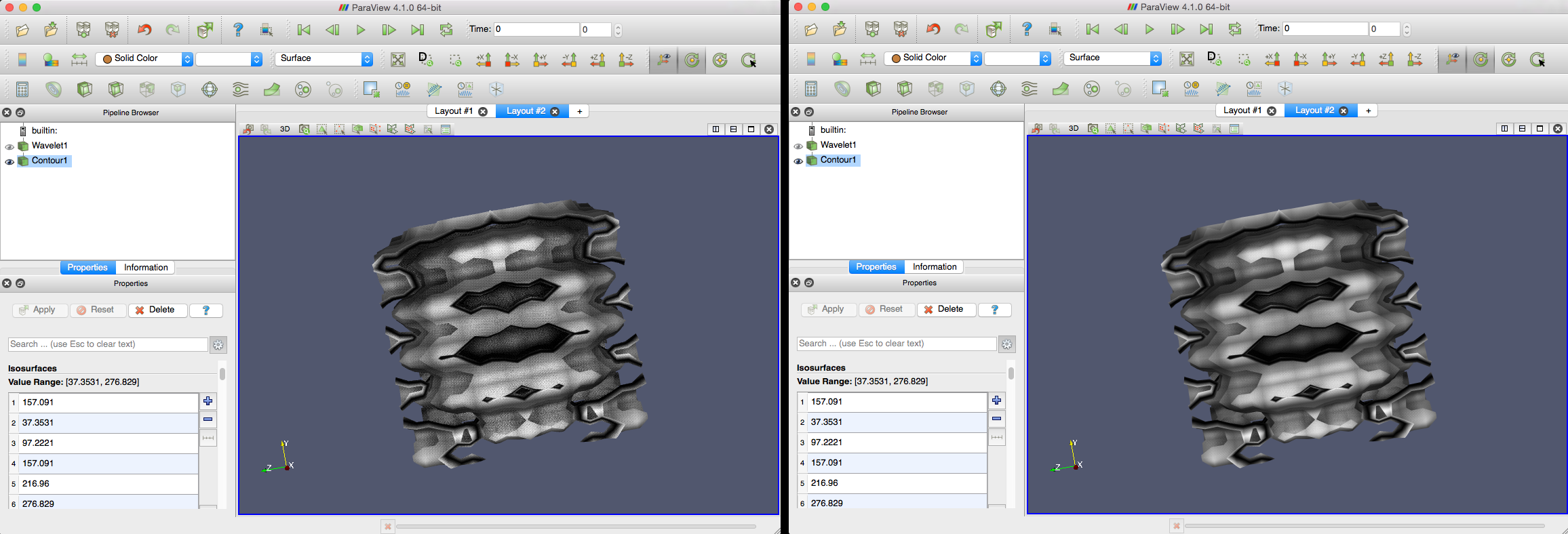
| OSPRay now renders the wavelet surface using sixty-four samples per pixel. |
|
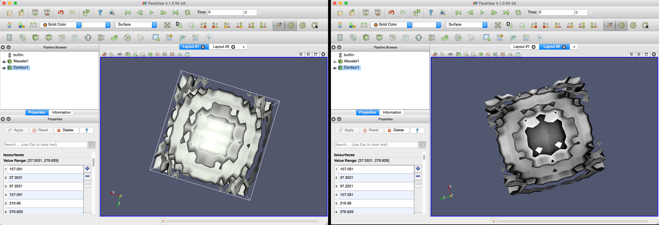
| Compare the image quality using four samples per pixel (left) versus sixty-four samples per pixel (right). |
|