Example 2: generating a scene file and rendering the scene
We now explain how to create a scene file and render the scene using a simple example with two domains of isosurfaces.
If you have not done so, edit the script file to set environment variables: examples/env_spray_linux.sh for Linux or examples/env_spray_macos.sh for macOS.
For Linux:
source examples/env_spray_linux.sh
For macOS:
source examples/env_spray_macos.sh
If you wish to skip the next two sections, copy the example scene file and go to the section titled “Rendering a scene of two wavelet domains.”
cp $SPRAY_HOME_PATH/examples/wavelet/wavelet_example.spray $SPRAY_HOME_PATH/examples/wavelet/wavelet.spray
Generating a scene file using ply files
Given ply files each associated with a domain, you can generate a scene file using the ply_header_reader tool and the plyfiles_to_scene.py script. ply_header_reader quickly parses only the header portion of a ply file to extract geometry information. plyfiles_to_scene.py takes all the ply files within a directory set by the user, and for each ply file, it uses the ply_header_reader tool to generate a domain section of the scene file.
The following is how you can generate wavelet.spray for the two ply files, wavelet0.ply and wavelet1.ply, located in $SPRAY_HOME_PATH/examples/wavelet.
Run the Python script to generate a scene file.
cd $SPRAY_HOME_PATH/scripts
python plyfiles_to_scene.py \
--loader $SPRAY_BIN_PATH/ply_header_reader \
--indir $SPRAY_HOME_PATH/examples/wavelet \
--out $SPRAY_HOME_PATH/examples/wavelet/wavelet.spray
If absolute paths are desired for ply files, you can simply append the --abspath option to the command line above.
Adding light sources to a scene file
With a scene file in place, you should manually add light sources somewhere in the scene file. If only ambient occlusion is used, no light sources are required so you may skip this step.
SpRay currently supports two kinds of light sources: a point light source and a diffuse area light source. Depending on the light type, you can add a light source using one of the following two lines.
light point <position x y z> <intensity r g b>
light diffuse <intensity r g b>
Each line with the light identifier is considered an independent light source in the scene file. For example, with the following statements in the scene file, SpRay will create a point light source and a diffuse light source upon loading the scene file.
light point -20 20 20 .2 .2 .2
light diffuse .1 .1 .1
The diffuse identifier defines a diffuse area light source that emits radiance uniformly over the hemisphere around the surface normal at each hit point on a surface. You can set the number of samples using the command line option --ao-samples.
Rendering a scene of two wavelet domains
After adding light sources to the scene file, you can render the scene similarly as you did for 64 wavelet domains. But this time, the render time may increase due to using multiple samples.
Depending on the mode you choose, run the script as shown below. N and n are optional, where N is the number of MPI tasks and n is the number of OpenMP threads for each MPI task. If these parameters are not set, 2 MPI tasks and 2 OpenMP threads per each task will be launched. For some special cases, the script discards N and n, using interally hardcoded values. For non-rendering modes, 1 MPI task and 1 thread are launched, and for the single-thread rendering mode, only 1 thread is launched with N MPI tasks. For the rendering settings used in this example, refer to the wavelet.sh script.
For film mode:
source $SPRAY_HOME_PATH/examples/wavelet/wavelet.sh film [N] [n]
Type a number from the application list.
Type a number from the shader list (ambient occlusion or path tracing).
display spray.ppm
For glfw mode:
source $SPRAY_HOME_PATH/examples/wavelet/wavelet.sh glfw [N] [n]
Type a number from the application list.
Type a number from the shader list (ambient occlusion or path tracing).
Type the q-key to close the window.
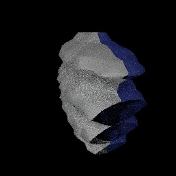
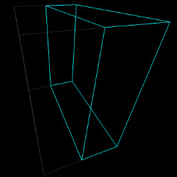
You should get something similar to the left image shown below. Noise in the image is caused by using a small number of samples. The right image shows the bounds of each domain: unhighlighted lines for the gray isosurface in one domain and highlighted lines for the blue isosurface in the other domain.
Example of a scene file
The file extension for a scene file is spray. The scene file describes light sources in the scene and the surfaces in each domain.
Here is a scene file you may have used to render the two isosurfaces. It has two light sources and two domains.
# filename: wavelet.spray

# light sources
light point -20 20 20 .2 .2 .2
light diffuse .1 .1 .1

# 0
domain
file wavelet1.ply
vertex 958
face 1748
bound 0 -10 -10 6.612539768218994 10 10
mtl diffuse 1 1 1

# 1
domain
file wavelet0.ply
vertex 909
face 1684
bound -6.036099910736084 -10 -10 0 10 10
mtl diffuse 1 1 1

# total vertices 1867
#total faces 3432
The following describes the meaning of each identifier in the scene file. The # symbol is used for single-line comments.
- light: a light source
- domain: a delimiter to create a new domain
- file: a ply file for the corresponding domain. If you don’t use the absolute path, the path where the file is located must be specified using the –ply-path command line option.
- vertex: number of triangle vertices in the domain
- face: number of triangles in the domain
- bound: minimum and maximum coordinates of the domain’s bounding box (e.g., bound
) - mtl: a material type for the domain
* Note: we will include a separate section about materials in detail (TBD).
Ply file format in SpRay
SpRay currently supports only ply files for surface data. As we can see in the header section of a ply file shown below, SpRay maintains coordinates and color values for each vertex of a triangle.
ply
format ascii 1.0
comment VTK generated PLY File
obj_info vtkPolyData points and polygons: vtk4.0
element vertex 909
property float x
property float y
property float z
property uchar red
property uchar green
property uchar blue
element face 1684
property list uchar int vertex_indices
end_header